Why Repairing a P6 Outdoor LED Display Matters & Common Failure Modes
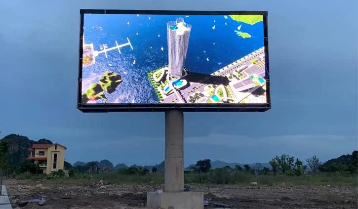
How To Repair P6 Outdoor led Display Sign Board Screen? A P6 outdoor LED display (pixel pitch = 6 mm) is widely used in advertising sign boards, facades, and outdoor signage because it balances visibility and cost. But over time, these displays degrade or suffer faults. Repairing instead of replacing saves money and downtime.
Common Failure Modes in P6 Outdoor LED Displays
Before diving into repair steps, let’s understand typical problems you’ll face:
-
Dead / dim LEDs / single pixel failures — one or more diodes no longer light, or a pixel is partially dark.
-
Module blackout / blank area — an entire module or section (cabinet) is not lighting.
-
Signal issues — communication interruptions, flicker, color blocks, garbled display.
-
Power failures / voltage drop — weak or broken power supply, power cables, or connectors.
-
IC / driver chip failure — the LED driver ICs on modules might burn out.
-
Bad solder joints / loose connectors — mechanical stresses, thermal cycling can loosen solder or connectors.
-
Environmental damage — moisture ingress, corrosion, UV, temperature extremes, dust, insects.
-
Controller / sending card / receiving card errors — the control system may have misconfiguration or hardware faults.
By knowing these, you’ll diagnose faster and avoid wasted effort.
Step-by-Step Diagnostic Process for a P6 Outdoor LED Screen
A systematic diagnosis saves time. Use the following process:
-
Visual & initial survey
-
Power off the display and inspect for physical damage, corrosion, moisture, burnt parts, broken connectors.
-
Power it on and note what pattern emerges — what parts are dark, flickering, colored blocks, etc.
-
Use test patterns (solid colors, grayscales, grid lines) to make issues visible.
-
-
Check power supply & voltage distribution
-
Measure voltage output of each power supply (should match spec, often +5V).
-
Check whether the module power cables are intact and securely connected.
-
In areas with blackout, check the input cable to the first dark module — maybe power is missing upstream.
-
-
Check signal chain / connectivity
-
Verify sending card, receiving cards, hub or decoder boards are functioning (look for indicator LEDs, communication status).
-
Check signal cables and connectors (ribbon cables, CAT cables, flat cables) for physical or electrical failure.
-
Swap or replug cables in the signal path to localize faults.
-
-
Isolate module-level faults
-
Once you know module(s) are causing trouble, you can remove or isolate them for repair.
-
Use a multimeter, continuity and resistance checks on modules, connectors, traces.
-
Confirm which LED(s), ICs or driver circuits are faulty.
-
-
Repair or replace at module / component level
-
Replace bad LEDs, resolder loose joints, swap driver ICs, or replace entire module if beyond repair.
-
Seal repairs to protect again from moisture.
-
-
Testing & calibration
-
After repair, test with known content and run full scans to verify uniformity, color matching, brightness.
-
If necessary, run calibration / brightness leveling among modules.
-
Monitor for some time to confirm reliability.
-
This systematic approach ensures you don’t chase the wrong component.
How to Repair Pixel / LED Failures & Module-Level Issues
Many common faults lie within modules themselves. Here’s how to approach them.
A. Replacing Dead or Faulty LEDs / Pixel Beads
-
Identify the failed pixel or LED bead (dark point, missing color).
-
Remove masking or cover (front or rear cabinet access).
-
If modules are front-service type, unscrew and remove module carefully.
-
Remove any protective gel (silicone, glue) around LED beads with tweezers or precision tools.
-
Use a soldering iron (low to moderate temp, short contact time) to desolder the old LED bead. Avoid overheating adjacent parts.
-
Insert a replacement LED bead (same spec, color, size), aligning polarity (positive vs negative).
-
Re-solder gently. Use conformal coating or neutral pH silicone to re-seal and protect the joint.
-
Reassemble the mask/module and test.
Tips / precautions:
-
Work under magnification (loupe) for precision.
-
Use ESD-safe tools and grounding to protect sensitive ICs.
-
Always use replacement parts with matching specifications (voltage, forward current, package).
-
Don’t overheat — typically limit soldering contact to a few seconds.
-
Maintain cleanliness — flux residue or foreign materials can cause shorts.
B. Replacing or Repairing IC / Driver Chips
If an entire row/column or block fails, it might indicate that the LED driver IC (or transistors) is bad.
-
Identify which IC controls the affected block (via module schematic or by observation).
-
Desolder the faulty IC (use proper technique, possibly a hot air rework station).
-
Place the correct new IC (same type/model) in position with correct orientation.
-
Solder and confirm all pins are making proper contact.
-
Re-test the module in situ.
Be cautious: IC replacement is more delicate — if misaligned or pins bridged, the module may fail further.
C. Repairing Broken Connectors, Traces & Solder Joints
-
Inspect module PCB traces near connectors or power pins — cracks or breaks sometimes occur due to vibration or thermal cycles.
-
Use fine wire (e.g. 30 AWG) to bridge broken traces where necessary.
-
Reflow or re-solder weak joints around connectors, pins, headers.
-
Check ribbon cable connectors and re-seat or replace if damaged.
D. Replacing the Entire Module
If module damage is extensive (multiple dead pixels, cracked PCB, water damage), it’s often more practical to replace the module.
-
Acquire the correct replacement module (same pitch, dimension, pinouts).
-
Align it correctly in the cabinet (ensure flat and well seated).
-
Connect power and signal connectors securely.
-
Seal around edges (gaskets, gasket glue) to protect from moisture ingress.
-
After replacing, test and calibrate color, brightness, alignment.
Some P6 modules are designed for front service or back service. Use the appropriate access direction. Many modern outdoor LED modules support front servicing — meaning you don’t need to pull the board from the back — which simplifies module replacement. (Examples of front-service P6.67 modules exist)
Repairing Power Supply & Signal / Controller Level Failures
Sometimes the issue is not module-level, but higher up. Here’s how to address:
A. Power Supply & Cabling Issues
-
Check the power supplies that feed the LED boards. If supply is weak, overloaded, broken — modules will fail.
-
Inspect power cables / bus bars / connectors for corrosion, broken wires, loose lugs.
-
Use a multimeter to measure voltage at each module input — ensure voltage matches spec (usually +5V or similar).
-
Where there is a significant voltage drop or a cable with high resistance, replace or repair the wiring.
-
Check for proper grounding, surge protection, fusing.
B. Controller / Sending Card / Receiving Card Errors
-
The sending card (controller) is the device feeding the video content to the LED system. If it fails or misconfigures, the screen may blackout or display artifacts.
-
The receiving cards or hub cards distribute the signal to modules within each cabinet. A configuration file (rcfg, .cfg) often is stored in receiving cards — replacing a receiving card with one that lacks proper config won’t work. Olympian LED explains this clearly: a receiving card must carry correct configuration.
-
Inspect indicator LEDs on these controller boards (power lights, communication lights) — their blinking patterns often indicate status/fault codes.
-
Reconnect or swap cables between sending and receiving cards to isolate faulty link.
-
Use the control software to ping modules or read back configuration to confirm if receiving cards are alive.
-
If a receiving card is bad, clone the config from a working one and program into the replacement before installing.
C. Signal Cable / Communication Link Failures
-
Check all signal cables (Ethernet, flat cables, CAT, shielded lines) for cuts, crimps, broken wires, pin misalignment.
-
Sometimes interference, signal attenuation, or poor shielding leads to flicker or loss. Use proper twisted shielded cables.
-
Re-route cables away from high-voltage lines or sources of EMI (motors, welding equipment).
-
Re-terminate or replug connectors — sometimes just reseating the cable restores function.
-
In some advanced systems, the system may support diagnostic ping or test patterns via software to check if modules are communicating.
Preventive Maintenance & Best Practices for Longevity
Repair is important, but prevention saves bigger costs and downtime. Follow these practices:
-
Regular inspections — at least quarterly, inspect seals, gaskets, module edges, connectors, and for moisture ingress.
-
Dust / debris removal — dust buildup traps heat and moisture; gentle cleaning, blowers, or compressed air help.
-
Protective coatings & conformal coating — apply moisture-protective coatings to module backs, sensitive joints.
-
Quality components — use modules, power supplies, cables, controllers from trusted brands with weather rating (IP65 / IP67).
-
Proper ventilation & heat management — heat is a major enemy; ensure airflow, fans, heat sinks.
-
Use surge protectors / lightning protection — outdoor signage is susceptible to voltage spikes, surges.
-
Correct installation & sealing — gaskets, silicone, waterproofing interfaces around cabinet seams.
-
Front-access design where possible — modules designed for front maintenance reduce time and dismantling.
-
Backup control hardware / configuration — keep spare boards and config files matching your system for rapid replacement.
-
Log module performance & keep history — track which modules often fail, environmental conditions, repair logs.
Case Example: Repairing a P6 Outdoor Sign Board – Walkthrough
Here’s a practical example to illustrate all the above in real life:
-
Symptom observation: A P6 outdoor sign shows a dark patch covering two modules (one above other).
-
Initial check: Confirm power is on, display control system is running. The rest of the display works except that patch.
-
Voltage test: Measure voltage at the first failed module input — it reads 0 V. That suggests power is not being delivered.
-
Trace back upstream: Check the power cable / bus feeding that column. Find one connector loose / corroded. Repair the connection. After reconnection, modules light partially (but flicker).
-
Signal test: Reseat the signal cable to that module sequence. It now shows static but with colored artifacts — suggests receiving card issue.
-
Receiving card swap: Remove that receiving card, program config from a working card, insert. The modules display properly now.
-
Pixel check: Still a few dead pixels remain in that area. Remove module and repair individual LED beads and one driver IC.
-
Sealing & testing: Reapply silicone, reseal module, reinstall, power up. Run test video, monitor for 24 hrs — all stable, uniform, no flicker.
This kind of layered repair — power → signal → module → fine adjustments — is how most repairs succeed.
Conclusion & Final Tips
Repairing a P6 outdoor LED sign board screen is feasible with patience, methodical diagnosis, and good tools. The key is to start wide (power, signal) then narrow down to module or component faults. Use proper replacement parts, protect your repairs from weather, and maintain log and backups for future fixes.
If you have the specific brand / model of your P6 sign (cabinet spec, control system brand, module layout), I can help you with the exact part numbers, replacement modules or wiring diagrams.